
Transformer protection
Preventing transformer explosions and fires at their source.
WATERWEB engineers nitrogen injection systems that prevent and extinguish fires in oil-filled transformers at power stations, substations and industrial plants, integrated with the transformer's protection relays and water spray system. It has also developed its own automatic fire alarm and explosion prevention systems for transformers.
Overview
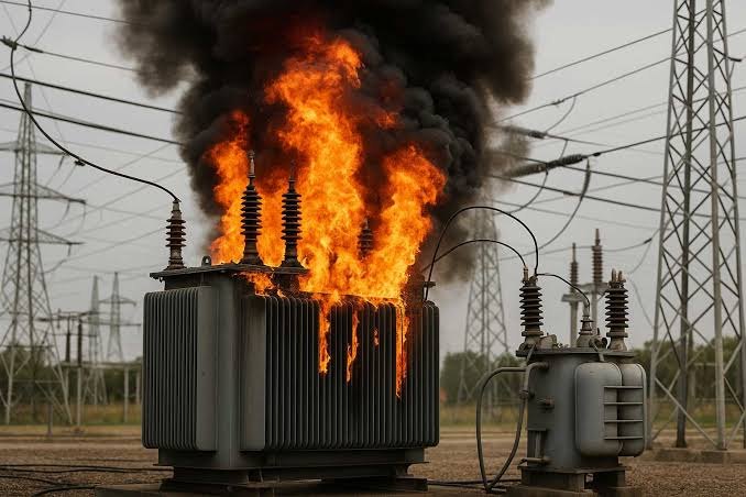
A power transformer is among the most valuable and least replaceable assets in any electrical installation. An internal fault can generate gas and pressure almost instantly, rupturing the tank or bushings and releasing burning oil. The resulting fire can destroy the transformer, spread to adjacent equipment and interrupt supply for months while a replacement is sourced.
Nitrogen injection addresses the problem inside the tank, where the fault originates. Whereas water spray fights a fire that has already broken out, nitrogen injection acts on confirmed fault signals to depressurise the tank and prevent a fire from developing. For larger units, CEA standards provide for both systems working together.
~4%
is the estimated probability of a fire over a transformer's 40-year service life, based on an annual risk of approximately 0.1 per cent.
How it works
To prevent unwanted operation, the system acts only when independent signals coincide: an electrical protection relay, a mechanical indication from the Buchholz or pressure relief device, and confirmation that the transformer has been disconnected. It then drains a controlled volume of oil from the top of the tank to relieve pressure, while a conservator isolation valve closes to stop oil feeding a fire. Nitrogen injected at the base of the tank stirs and cools the oil, removing the conditions for ignition. Fire detectors on the tank cover provide an additional trigger for extinguishing mode.
Key components
- Control cubicle
- Houses the nitrogen cylinder, oil drain valve and injection valves.
- Control box
- Monitors the signals and executes the prevention or extinguishing sequence.
- Conservator isolation valve
- Stops conservator oil from feeding a fire after a rupture.
- Fire detectors
- Heat sensors mounted on the tank cover.
- Oil drain and pit
- Carry drained oil safely away from the transformer.
- Nitrogen injection points
- Admit nitrogen at the base of the tank to stir and cool the oil.
- Relay interfaces
- Links to Buchholz, pressure relief, differential and trip circuits.
Configurations
| Type | Application |
|---|---|
| Nitrogen injection | Prevention and extinguishing inside the tank, acting on confirmed fault signals. |
| High-velocity water spray | External extinguishment and exposure protection once fire has developed. |
| Combined protection | Both systems together, typically for high-voltage transformers of strategic importance. |
| Separation and fire barriers | Spacing or fire-rated walls that prevent fire spreading between units. |
Engineering considerations
Signal logic
Signal combinations chosen to act on genuine faults and ignore spurious relay operations.
Oil drain volume
Sized to relieve pressure while keeping the core and windings submerged.
Nitrogen capacity
Cylinder capacity matched to the transformer's oil volume and tank geometry.
Utility specification
Compliance with CEA regulations and the technical specification of the utility or owner.
Integration
Coordination with the transformer manufacturer, protection engineers and any existing water spray.
Testing without disruption
Commissioning by simulation, with no oil drained from a live transformer.
Typical applications
- Generator and station transformers at power stations
- Grid and industrial substations
- Solar and wind pooling substations
- Large industrial transformers
Protection is specified according to the transformer's rating, oil volume and location.
Scope of delivery
Assessment
Review of transformer data, relays and existing protection.
Design
Drain-and-stir nitrogen injection and fire detection.
Supply and installation
Control cubicle, nitrogen cylinder and valves.
Integration
Interlocks with Buchholz, pressure relief and trip relays.
Maintenance
Verification of cylinder pressure, valves and signals.
Owner responsibilities
Most inspection findings trace back to simple checks missed between service visits. The items below fall to the owner; every WATERWEB maintenance report adds the checks specific to the site.
- Check nitrogen cylinder pressure monthly
- Keep the control cubicle closed and dry
- Never bypass interlocks after maintenance
- Notify WATERWEB after any transformer trip or oil handling work


Frequently asked questions
How does nitrogen injection work?
On receipt of confirmed fault signals, the system drains a controlled volume of oil to relieve tank pressure and injects nitrogen at the base of the tank. The nitrogen stirs and cools the oil, preventing explosion and fire.
Does nitrogen injection replace water spray?
No. Each acts at a stage of the fault that the other cannot reach. CEA standards provide for both on larger transformers, and utilities and insurers may require them together.
Is there a national standard for nitrogen injection systems?
Not yet. The CEA has issued a generic specification pending a Bureau of Indian Standards (BIS) standard, and utilities apply their own technical specifications. WATERWEB designs to the specification that governs each project.
Planning a new facility, or assessing an existing system?
A WATERWEB engineer will review your drawings or survey the site, assess it against the governing code and set out recommendations in writing.